

Diagnosing Parasitic Loads
With increasing electronic controls in modern trucks, parasitic loads are becoming a larger concern for today’s fleets, especially in fleets where vehicles may be parked for long periods of time. With so many electrical circuits in these vehicles, any one of them may be a culprit, making diagnosing a bit like looking for a needle in a haystack. A strong understanding of electrical theory is a key to successfully diagnosing a parasitic load.
 There are multiple factors that can increase parasitic load on a vehicle. A parasitic draw occurs when components, or their circuits, are causing a power drain on the battery after the vehicle has been turned off. Faulty components, like a bad alternator diode, can cause excessive draw. Aftermarket components can also cause excessive draw, as they can put a strain on the battery that was not taken into consideration when the vehicle was first built.
You can test for excessive parasitic battery draw with a digital multimeter. With the ignition off, set the multimeter to DC Amps, and connect the test leads in series between the battery negative posts and clamp. If available, refer to manufacturer specifications for maximum parasitic draw. If specifications are not available, a good guide for figuring maximum parasitic load is to divide the reserve capacity of the vehicle’s battery/ies by four. If you find that you have excessive draw, you can use the process of elimination to identify possible circuit problems. Remove fuses one at a time and check for a drop in parasitic draw. When a removed fuse reduces the parasitic draw, you have narrowed the draw to that fuse’s circuits.
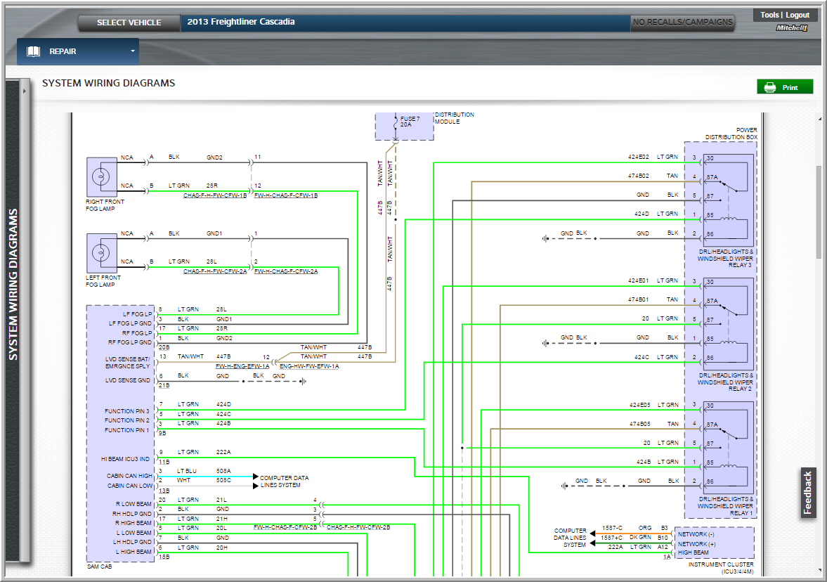
With modern electronic engine controls, there are many more systems that can cause a parasitic load to occur in trucks now than in years past. Technicians must have the knowledge and tools to successfully diagnose issues that may arise. Tools like the wiring diagrams in Mitchell 1’s TruckSeries repair information software can be a great help with diagnosing parasitic loads and related issues. Being able to highlight or isolate circuits in question can help make it easier to find the correct diagnosis (figure 1). Then it’s just a matter of confirming your diagnosis and correcting the problem, something the TruckSeries repair information can also help with if you need step-by-step procedures (figure 2).

Figure 1 – Sample of a TruckSeries Wiring Diagram with Circuits Highlighted and Isolated (click to expand image to full size)
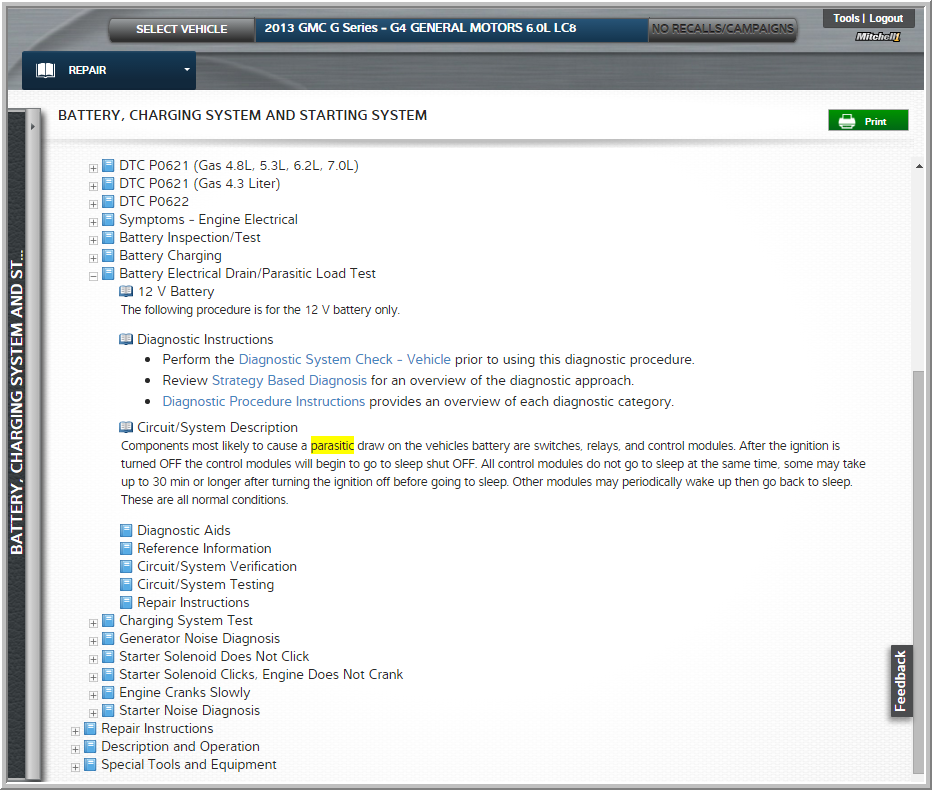
Figure 2 – Sample of Parasitic Load Diagnostic & Repair Information in TruckSeries (click to expand image to full size)